Monday 1 April 2013

Interior Design

Introduction to Audio System

Audio System is a system of electronic equipment for recording or reproducing sound.
The first influence upon the car audio system was the radio. Invented in the early 1900's (around the same time cars became popular) it however didn't gain commercial status until the 1920's when the first commercial boomed occurred.  In 1922, a historic date for the car audio system, George Frost was the first person known to experiment with car radio with his own Ford car. Then in 1925, the first official listing of a car radio occurred, which was followed in 1927 with the first mass produced car radio, the Transitone TH-1.


1930: First Commercial In-Car Radio
The history of car audio dates back to the 1930s, when the Galvin brothers introduced the first car radio, named Motorola ('motor' meaning motion and 'ola' meaning sound). Innovations kept happening in many parts of the world. It took another forty years to develop audio amplifiers, in a quest to develop something just more than a radio. Since then, there have been more and more sophisticated devices which can stand the temperatures and vibration of automobiles. Modern speakers are not even visible, but produce good acoustics and sound quality.
original 1952: First Radio With FM


AM was the undisputed king of the airwaves in 1952, but that didn’t stop Blaupunkt from introducing the first in-car FM radio.

1953: Becker Mexico Introduced
Becker’s iconic Mexico radio launched this year, arguably the first premium in-car radio. It had AM/FM and the first fully automatic station-search button.
1955: First “Music On Demand”
Starting in 1955, Chrysler offered a small turntable in its high-end cars, playing proprietary seven-inch records with about 45 minutes of music. It was a bust.
1963: First All-Transistor Radio
A number of manufacturers introduced transistors to their aftermarket car radios in the early 1960s, but Becker’s Monte Carlo was the first to be fully “solid state”—no vacuum tubes.
1965: First Eight-Track Tape Player
Predecessor to the cassette, the eight-track was a loser from the start and was dead by the early ’80s. Ford and Motorola jointly introduced in-car eight-track players this year.
1969: First Stereo
Becker’s Europa was the first in-car stereo setup, with the tuner amplifying two channels instead of one.
1970–1977: Cassette-Tape Players
The rollout of cassettes allowed for one of mankind’s greatest achievements: the mix tape. This development also heralded the creation of branded aftermarket cassette-tape players from Alpine and Pioneer, among others.
1982: Bose Becomes First Premium Stereo System
Bose and GM’s Delco teamed up to offer the first “designer” stereo system. Bose sank money into car-specific development; rather than just producing an expensive head unit, it was marketing the entire system to Oldsmobile, Buick, and Cadillac shoppers.
1985: First Factory-Installed In-Dash CD Player
While Sony had introduced an in-dash player the previous year, Becker’s Mexico Compact Disc was the first to be factory installed (in Benzes, of course). 


Component Identification


The Head Unit


The head unit refers to the main device that serves as the source of the sound or simply the radio that is installed in the car's dashboard. The unit has a radio receiver and tuner component that receives radio frequencies through an antenna. The tuner is used to select or adjust radio frequencies or broadcast bands. The unit has other components, such as a disc player that plays different types of disc formats, a preamplifier that sends sound signals to the speakers and an equalizer that shapes the sound. The radio unit has an interface for control over the unit's different functions such as the volume and menu functions. The head unit is powered by the car's electrical distribution system. Wires and cables also connect the head unit to all the other components in the audio system.

Read more: How Does a Car Audio System Work? | eHow.com http://www.ehow.com/how-does_4928715_car-audio-system-work.html#ixzz2Q2XhnK8t
The Amplifier


A car stereo system has to have an amplifier to increase the power of an audio signal so it's strong enough to move the speakers and create sound. Amplification is a two-stage process handled by a preamp and a power amplifier.
The preamp is usually housed inside the head unit and takes data from a radio, CD player or other audio source and prepares it for the power amplifier. This process includes slightly boosting the audio signal, which makes it compatible with the input of the power amplifier and ensures that it's resistant to noise that can radiate from other electronics in a vehicle. The power amplifier then takes the preamp's low-level signal and significantly boosts it so it can move the speakers and create sound.
Many head units have a small, built-in low-power amplifier that can "drive" smaller speakers. This allows the audio system to be reduced to just a head unit and a few speakers. But better sound requires more power. So higher-end systems have separate power amplifiers that are mounted away from the head unit due to their size and the heat they generate. We cover the details of "outboard" amplifiers in a separate article in this series.
The Speakers


A speaker is important to the final output of an original car audio system. Just like the singer’s voice, a sweet voice will produce fantastic sound output. The role of the speakers is to convert audio electrical signal to a sound signal and let the signal radiates in the surrounding medium. The volume can be adjusted by using either an appropriate knob or buttons on the head unit. Changes can also be made to the amount of base and treble being supplied by the speakers. The head unit makes these changes by adjusting the pitch and frequency output for the speakers. The most common design for car speakers is the tapered design. This is because of the space limitation inside the vehicle for car stereo installation. The tapered design makes it possible to expand the effective area of the diaphragm, and this effective area determines the low frequency response of the speaker. In other words, the tapered design can enhance the bass effect if a car radio system without the installation of bass case..

Crossovers

A crossover is used to distribute the audio between the various speakers in your car audio system. They are available in two varieties which are active and passive.


Active Crossovers
Active crossovers are placed between your car stereo output and the amplifiers feeding your speakers. They offer many advantages over their passive counterparts. Most crossovers offer the ability to alter the frequency ranges and levels dedicated to each amplifier. The main disadvantage is that they are more expensive than their passive counterparts.


Passive Crossover

Passive crossovers consist of capacitors and inductors. A capacitor's impedance reduces as the frequency increases whereas an inductor's impedance increases with frequency. These characteristics can be used to filter the frequencies fed to each speaker in the system. The choice of these components is very simple and can be found using some simple equations.
The advantages of a passive crossover is that they are very cheap, easy to build and can be tailored exactly to your requirements.
The disadvantages are that they have to be placed between the amplifier and the speaker. This introduces a loss in the system which means less power to the speakers! Another disadvantage is that the crossover is tailored to a set of speakers. If these speakers are changed the crossover may require redesigning.


Equalisers


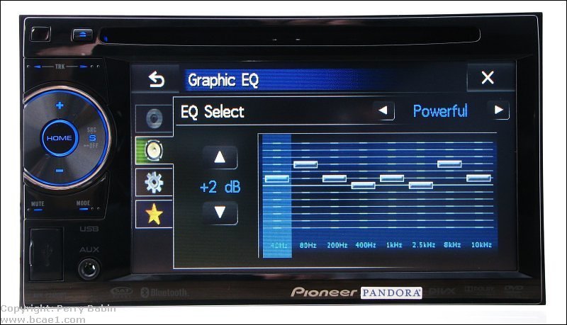
An equaliser enables the frequency response of the system to be 'tweaked'. It allows adjustment of various frequencies across the audio spectrum for example 20, 40, 80, 160, 315, 630 Hz and so on.
The purpose of an equaliser is not to fix problems with the system such as too much mid range or too much bass. If this is the case these issues should be addressed by reducing and increasing the appropriate amplifier gains. An equaliser should be used to flatten the audio response of the entire system. This means that if it is used correctly the gain/cut controls should remain very close to the centre.

Basic Operation


This diagram shows the head unit's RCA output jacks driving the RCA inputs of the amplifier. The signal is a full range signal which, as you can see, is reflected in the frequency response graph. It shows that all of the frequencies across the audio spectrum are being reproduced at the same level. The relative signal levels of the head unit's output and the amplifier's output are shown by the sine waves in the upper right hand corner of the diagram. You can see that the output from the amplifier is larger in magnitude (because the amplifier amplifies the head unit's output signal). In a real system, the difference in magnitude between the two waveforms would actually be much larger than shown but you get the picture (or the diagram :-).


Benefits Of Audio System

In this day and age, practically everybody can drive. The need to travel around for work as well as for leisure purposes has meant that driving has become almost an essential skill needed for everyday life. The fact that we do use our cars so often means that we can sometimes get a little bored of driving. That is when a slight distraction is needed to keep us focused and to make driving that little bit more pleasurable. This distraction generally comes in the form of a car audio system. A car audio system allows you to listen to your favorite music whilst you are driving. 
Safety Feature

1.1 Introduction
Safety feature of a car is that a percentage of the car can protect its driver and passenger when driving also when have a crash or accident. Not only that, It also about a probability for the car to avoid an accident in the first place. 
The safety feature can be group into two:

Primary safety describes features designed to help you avoid a crash. Brakes and lights fall into this group as well as systems like electronic stability control or lane keeping support.
Secondary safety features come into play once you have an accident and are designed to reduce injuries to you and your passengers. This covers seat belts and airbags, head restraints and the design of the bodyshell and vehicle interior.


  • 1.2 Discussion

    1.2.1 Air Bag

    1.2.1.1 History of air bag


    The first steps towards today's airbag were taken by John W. Hetrick, a retired industrial engineering technician, in the early '50s. Following a car accident involving Mr. Hetrick and his wife and daughter, he thought of a device that would prevent passengers from hitting the inside of a car. 

    He received a patent in 1953 for something called "safety cushion assembly for automotive vehicles." At about the same time, German inventor Walter Linderer received a patent for a similar prototype. Mr. Linderer's product was using a compressed air system, which could be either released by bumper contact or by the driver.

    Following the two patents, Ford and General Motors started tinkering with inflatable restraints, but they were faced with two big problems. One of them was related to the detection of a collision and the inflation of the airbag, which took too long to work properly. The second issue was that the airbags themselves would cause secondary injuries to passengers. 

    ⌕ Airbag schemeIt wasn't until the late 1960's that the airbag development made some real progress. The man responsible for this? A New Jersey mechanical engineer by the name of Allen K. Breed. He invented what is considered the world's first electromechanical automotive airbag system in the form of a crash sensor. 

    Mr. Breed would later on come up with another important development in the field, namely the airbag that vents air as it inflates, reducing the risk of secondary injuries by reducing the inflated bag's rigidity. 

    Soon after that, Ford built an experimental airbag fleet (1971), while General Motors tested airbags on a 1973 model Chevrolet, albeit only sold for government use. The year 1973 brought the first passenger car fitted with an airbag for the general public, this breakthrough arriving as a 1973 Oldsmobile Toronado. One year later, Buick, Cadillac and Oldsmobile offered dual airbags as an option on several of their full-sized models. Mercedes-Benz was the first to offer the modern airbag as an option on their S-Klasse model. 

    The big difference between the US and German approach was that while Ford and GM marketed their airbags as an alternative to the seatbelt, Mercedes-Benz combined the two safety devices for more efficiency in preventing in injuries. 

    The first side and torso airbags became optional in 1995 on Volvo's 850 models. Three year later, the US federal government mandated dual frontal airbags on all passenger vehicles. The first airbag system for motorcycles came from Honda in 2006. 

    1.2.1.2 Background Information


    An air bag is an inflatable cushion created to protect passengers and drivers from serious injury in the case of a collision. The air bag is part of an inflatable restraint system, also called an air cushion restraint system (ACRS) or an air bag supplemental restraint system (SRS), because the air bag is designed to supplement the protection offered by seat belts. Seat belts are still needed to hold the occupant securely in place, especially in side impacts, rear impacts, and rollovers. Upon detecting a collision, air bags inflate instantly to cushion the exposed occupant with a big gas-filled pillow.
    A typical air bag system consists of an air bag module (containing an inflator or gas generator and an air bag), crash sensors, a diagnostic monitoring unit, a steering wheel connecting coil, and an indicator lamp. These components are all interconnected by a wiring harness and powered by the vehicle's battery
    The crash sensors are designed to prevent the air bag from inflating when the car goes over a bump or a pothole, or in the case of a minor collision. The inflator fits into a module consisting of a woven nylon bag and a break-away plastic horn pad cover. The module, in turn, fits into the steering wheel for driver's-side applications and above the glove compartment for front passenger applications.
    In a frontal collision equivalent to hitting a solid barrier at nine miles per hour (14.48 kilometers per hour), the crash sensors located in the front of the car detect the sudden deceleration and send an electrical signal activating an initiator (sometimes called an igniter or squib). Like a light bulb, an initiator contains a thin wire that heats up and penetrates the propellant chamber. This causes the solid chemical propellant, principally sodium azide, sealed inside the inflator to undergo a rapid chemical reaction (commonly referred to as a pyrotechnic chain). This controlled reaction produces harmless nitrogen gas that fills the air bag. During deployment the expanding nitrogen gas undergoes a process that reduces the temperature and removes most of the combustion residue or ash.
    The expanding nitrogen gas inflates the nylon bag in less than one-twentieth (1/20) of a second, splitting open its plastic module cover and inflating in front of the occupant. As the occupant contacts the bag, the nitrogen gas is vented through openings in the back of the bag. The bag is fully inflated for only one-tenth (1/10) of a second and is nearly deflated by three-tenths (3/10) of a second after impact. Talcum powder or corn starch is used to line the inside of the air bag and is released from the air bag as it is opened.


    1.2.1.3 Component Of Air bag


    The three major component which is important are sensor, inflator and air bag. 

    Sensor is important in order to determine when a collision has occured which will operate at the lower severity. It is basically function for detecting a collision when it is occur. In other word,it is a mechanism that tells the bag it's time to inflate, which generally requires the equivalent force of running into a brick wall at 10 - 15 mph. However, sensors in newer airbag systems are designed to determine whether or not there is a person in the front passenger seat and whether or not the passenger has enough weight for the bag to be safely deployed.

    Inflator are designed to provide the gas to inflate the air bag after the sensor have determined that a collision has occured. 
    There are 3 main type of inflator: 
    1. The stored-gas generator : consist of gas stored at high pressure in a tank and supplied to the air bag through a fast adding valve and manifold.
    2. Gas generation system : consist of propellant or fast-burning powder which generates the gas from burning.
    3. The hybrid system : consist of a combined stored gas system and gas generation system.

    Airbag are usually made of a coated nylon and must be strong enough to withstand the forces generated by the measure and the opening force.

    1.2.1.4 Basic Operation


    Ignition judgement and conditions

    (1)Front collision


    When both the deceleration sensor and safing sensor in the center airbag sensor assembly turnon, the driver airbag, front passenger airbag and seat belt pretensioners are ignited.The center airbag sensor assembly switches the threshold level that should be activatedaccording to the signal from the front airbag sensors (front satellite sensor).The safing sensor of the center airbag sensor assembly is designed to be turned on by asmaller deceleration rate than the deceleration sensor.There used to be a three sensor type in which the driver airbag, front passenger airbag and seatbelt pretensioners were ignited when the front airbag sensor turned on or the decelerationsensor in the center airbag sensor assembly turned on, and the safing sensor in the center airbag sensor assembly turned on.There also used to be a one sensor type that had no front airbag sensor and performed all thecontrol only with the airbag sensor assembly.

    (2)Front side collision


    The safing sensor of the center airbag sensor assembly is designed to be activated by a smaller deceleration rate than the deceleration sensor of the side airbag sensor. As illustrated, ignitionof the side airbag and curtain shield airbag is caused when current flows to the initiator, whichhappens when a safing sensor and the deceleration sensor go on simultaneously.Some model with E-type SRS airbags have a safing sensor in the side airbag sensor.Vehicle with side door sensor When the safing sensor in the center airbag sensor assembly turns on and the deceleration sensor in the side door sensor or in the side airbag sensor is on, the side airbag and curtainshield airbag are ignited.

    (3)Rear side collision


    When both the safing sensor and the deceleration sensor in the curtain shield airbag sensor turn on, the curtain shield airbag is deployed.Some models have a safing sensor outside the curtain shield airbag sensor and control with thesafing sensor in the center airbag sensor assembly.

    1.2.2 Chrysler Air Bag System


    Every Chrysler 200 Convertible is equipped with standard advanced airbag systems. Front multistage airbags and front seat-mounted side airbags.
    This provide enhanced side protection for the driver and front passenger and also deploy with appropriate force based on the severity of the impact.
    Steering System

    Introduction to Steering System

    Steering system is defined as a system to control the direction of the front wheel over all types of road conditions, through turns and at different speeds. It is made of a linkage system that is attached to the front wheels, the steering wheel and the steering gear. The function of the steering system is control of front wheel (sometimes rear wheel) direction, transmit road feel (slight steering wheel pull caused by the road surface) to the drivers hand, and absorb most of the shock going to the steering wheel as the tire hits holes and bumps in the road. Manual and power steering unit is commonly used today. The basic operation is that, as the driver turns the steering wheel, the steering gear transfers this motion to the steering linkage. The steering linkage turns the wheel to control the vehicle direction.


    Discussion


    1.1 Manual Steering System


    History :


    It’s 1956 and the 20-inch-diameter steering wheel on a Chevrolet Bel Air or Ford Fairlane provided the leverage to steer the wheels. But, it was especially difficult to turn the steering wheel when the vehicle was stopped. Turning the wheel required a certain amount of upper body strength that was given by God to truck drivers of the day.
    When the Saginaw recirculating ball steering gear was introduced on the 1940 Cadillac, it provided a little more mechanical advantage, but it was still hard to turn the wheel when the vehicle was stopped. If the car makers of the era were going to sell more vehicles, especially to the new suburbanite homemakers, they were going to have to be easier to steer and shift. The premium vehicles, Cadillac, Lincoln and Chrysler, were adding power steering to their optional and standard equipment lists, but they were still the most expensive cars in the dealers’ showrooms.


    1.1.1 Integral Steering Gear System

    Basic Operation

    In operation, as the steering shaft is turned, the wormshaft also turned. The wormshaft have spiral grooves on the outside diameter. The ball nut which has mating spiral grooves inside is placed over the wormshaft. Small steel balls circulate in the mating grooves and bal guides. As the ball moves through the grooves and out, they return to the other side through guides. This system provide a low friction drive between the wormshaft and ball nut. Teeth on the ball nut mesh with the teeth on the sector shaft. The sector shaft is also known as pitman shaft. As the wormshaft is rotated, the ball nut moves back and forth, to the left and right. As the ball nut moves back and forth, it causes the sector shaft or pitman shaft to rotate through partial circle. The sector shaft is connected directly to the pitman arm which control the linkage.

    1.1.2 Rack And Pinion Steering Gear System


    Basic Operation


    When the steering wheel and steering shaft turn, the pinion gear meshes with the teeth on the rack. This causes the rack to move left and right in the housing. This motion moves the remaining steering linkage to turn the front wheels. This system is very practical for small cars that require lighter steering capacity. It is a direct steering unit that is more positive in motion than the standard steering linkage.


    1.1.3 Standard Steering Linkage


    Basic Operation

    The steering linkage is defined as the pivoting parts necessary to turn the front wheels. The linkage connects the motion produced by the pit man shaft to the front wheels on the vehicle.
    The motion from the steering gear and the sector shaft or pit man shaft causes the pit man arm to rotate through a partial circle ( reapprocating motion or back and forth). This motion causes the center link to move back and forth also. The idler arm is attached to the frame of the vehicle for support. Tie-rods are connected to each side of the center link. As the center link moves, both tie-rods move. The tie-rods are then attached directly to the steering knuckle and wheel for turning. Adjusting sleeves are placed on each tie-rods for adjustment.

    1.1.2 Component of Manual Steering System

    Pit man Arm

    image of a Pitman Arm
    Pit man Arm can be the wear or non wear type. The wear type pit man arm has a tapered ball stud that is connected the center link. The other end is mounted on the steering gear sector shaft. The non wear style pit man arm has a tapered hole and seldom needs replacement.

    Center Link
    image of a Drag Link/Center Link
    Use for connect by other linkage. The point of connection can be the pivot point, stud end, bushing end and open taper end.

    Idler Arm
    image of a Idler Arm
    Constant torque type which use synthetic bearing to reduce friction and road shock. The bearing are preload and preset at the factor. So that, constant torque type can has very low friction characteristic.

    Tie-rods End
    image of a Tie Rod End
    Have a rounded ball stud to allow both lateral and vertical movement. The tension spring inside the tie-rods end is used to reduce road shock throughout the steering system.

    Adjusting Sleeve

    Ensure that adjustment can be done without disassembling the tie-rods and also to lock the tie-rods together.

    1.2 Power Steering System

    Purpose of power steering system is to make steering easier for the driver especially on heavier vehicles. It is design to reduce the effort needed to turn the steering wheel. Not only that, it also reduces driver fatigue and increase safety during driving.


    1.2.1 History of Power Steering System


    The power steering was invented by a man named Frances W. Davis. While there have been many modifications since the implementation of power steering, for the most part, Davis is the “father” of power steering.
    In 1927 GM installed one of Davis’s power steering designs in a truck that was used at a Michigan coal mine. The driver was ecstatic as he could actually turn the steering wheel of his fully loaded truck with only two fingers. Based on that feedback GM began to formulate a plan to incorporate power steering into their fleet.
    By 1932 the Cadillac division of GM had a fully operational power steering unit ready to go into some 15,000 units for the upcoming model year. However, when GM calculated and then recalculated the cost of tooling and installation to those 15,000 units they quickly deemed the cost too much for the public to absorb and the program was dropped. Needless to say, this is where GM and Davis parted ways.
    For all intensive purposes, that could have been the end of the power steering mechanism that Davis had developed, but Davis was not one to give up so easily. He went to work for Bendix and in 1939 he found himself back at GM only his time working in the steering division of Buick.
    Then Pearl Harbor happened and the military began to install Davis’ power steering design in some of the tanks they built to fight in the war. After the war was over Davis returned to Cadillac and tried his luck again, but was once again shot down as the Cadillac people said their cars were in such demand that they simply didn’t need his power steering unit.
    Then in 1951 the unthinkable happened. Chrysler introduced the Hydraguide based on some of Davis’ expired patents. This quickly became the talk of the industry and the talk of every American town. But because the design was made with patents that were expired Davis received nothing as a result. It seemed that all his hard work would prove to be for nothing.
    But fate has a funny way of playing games sometimes and soon thereafter Davis got a call from the GM big boys giving him full reign over the new power steering division. One year later the 1952 Cadillac came out with power steering based on Davis’ design. Because these patents were not expired Davis got a piece of every power steering pie that GM produced.


    1.2.2 Basic Component of Power Steering System

    Hydraulic Pump


    Function to produce fluid pressure. The pump is driven by a belt running from the crankshaft. It supplies the hydraulic pressure needed to operate the steering gear.

    Power Steering Pump

    Constant or Positive displacement Pump. They deliver different pressure depending on the type and make of the vehicle. They use special power steering fluid recommended by the manufacturer.

    In operation, as the center part of the pump turns clockwise, there is a suction produced where the return oil comes in. The suction is produced because at this location, the eccentric area gets larger and larger. Then, because the area gets smaller, a pressure is produced.

    Control Valve

    It is build directly into the power steering gear assembly to direct the air pressure to one side or the other on the piston and the ball nut assembly. When the steering wheel is turned, the control valve is position in such a way as the direct oil to the correct location. There are two type of control valve:

    i) Rotary Spool Valve


    Operation:
    When the steering wheel is turned, the twisting effort produced through a torsion bar to rotate the internal spool slightly. This is done on an internal spline. As the spool rotates slightly, a different set of ports is opened and closed to allow oil pressure to flow to the correct side of the piston assembly.

    ii)Sliding Spool Valve

    Operation:
    When steering wheel and worm gear is turned, the sliding spool valve moved slightly by linkage attached to the worm gear shaft. The internal spool open a set of ports to allow high pressure fluid to enter the correct side of the piston and the ball nut assembly.


    1.2.3 Integral Power Steering System


    Basic Operation :

    As the worm gear is turned by the steering wheel, the oil pressure is sent to the unit from the power steering pump. Oil is sent to both sides of the piston. This keeps the piston in a stable position. When the car is moving in a straight line, the pressure are equal on both sides of the piston. When the steering wheel is turned, higher oil pressure is directed to one side or the other to assist movement of the piston and the ball nut assembly. Assisting the movement of this assembly makes it easier for the driver to turn the steering wheel.

    1.2.4 Rack And Pinion Steering System


    For the Rack and Pinion Steering, the pressure from control valve operates the rack assembly. It uses the same principle as the Integral Power Steering.

    Basic Operation :
    As the power steering pump produces the necessary hidraulic pressure, the fluid is sent to the rack-and-pinion steering gear. The pressure difference across the piston in the center assists the effort on the steering wheel.

    1.3 Electronic Power Steering System


    Basic Operation : 

    As an electrical motor is placed into Rack and Pinion Power Steering, as the motor is turned, it assists the movement to the Rack and Pinion components. Steering effort is greatly reduced and is taken by the motor. It is because the motor are able to rotate in both direction. However, the motor is controlled by a sensor placed in rack and pinion housing , near steering column. 

    As the driver begin to turn the steering wheel, hydraulic pressure is built up. The increase in pressure is sensed by the steering effort sensor. The sensor is able to select the direction of the motor movement and turn the motor off and on accordingly.


    So, in conclusion, as the steering wheel is turned, the steering sensor tells the Electronic Power Steering control unit to send hydraulic fluid and pressure to the steering gearbox. This action assists the steering effort when turning the front wheels.


    Advantage of Electronic Power Steering System


    One of the advantages of electric power steering is that it eliminates the power steering pump, which can use as much as 8 to 10 horsepower under load. This improves fuel economy while also eliminating the weight and bulk of the power steering pump and hoses. Getting rid of the hydraulics also does away with fluid leaks and the need to check the power steering fluid. Electric power steering is also quieter than hydraulic systems because there is no pump noise and no fluid flowing through hoses and valves. But the most noticeable difference is in handling and steering refinement.
    Electric power steering can be fine tuned with a precision that is hard to match with hydraulic controls. By monitoring the driver's steering inputs, vehicle speed, and other suspension dynamics, the system can provide just the right amount of steering feel and effort to match rapidly changing driving conditions. EPS can deliver extra effort when you need it, and reduce steering effort when you do not need it. It can even provide steering assist when the engine is off.
    So, it ensure the comfort of the chrysler car while driving it.