Introduction to Steering System

Steering system is defined as a system to control the direction of the front wheel over all types of road conditions, through turns and at different speeds. It is made of a linkage system that is attached to the front wheels, the steering wheel and the steering gear. The function of the steering system is control of front wheel (sometimes rear wheel) direction, transmit road feel (slight steering wheel pull caused by the road surface) to the drivers hand, and absorb most of the shock going to the steering wheel as the tire hits holes and bumps in the road. Manual and power steering unit is commonly used today. The basic operation is that, as the driver turns the steering wheel, the steering gear transfers this motion to the steering linkage. The steering linkage turns the wheel to control the vehicle direction.

Discussion
1.1 Manual Steering System
History :
It’s 1956 and the 20-inch-diameter steering wheel on a Chevrolet Bel Air or Ford Fairlane provided the leverage to steer the wheels. But, it was especially difficult to turn the steering wheel when the vehicle was stopped. Turning the wheel required a certain amount of upper body strength that was given by God to truck drivers of the day.
When the Saginaw recirculating ball steering gear was introduced on the 1940 Cadillac, it provided a little more mechanical advantage, but it was still hard to turn the wheel when the vehicle was stopped. If the car makers of the era were going to sell more vehicles, especially to the new suburbanite homemakers, they were going to have to be easier to steer and shift. The premium vehicles, Cadillac, Lincoln and Chrysler, were adding power steering to their optional and standard equipment lists, but they were still the most expensive cars in the dealers’ showrooms.
1.1.1 Integral Steering Gear System

Basic Operation
In operation, as the steering shaft is turned, the wormshaft also turned. The wormshaft have spiral grooves on the outside diameter. The ball nut which has mating spiral grooves inside is placed over the wormshaft. Small steel balls circulate in the mating grooves and bal guides. As the ball moves through the grooves and out, they return to the other side through guides. This system provide a low friction drive between the wormshaft and ball nut. Teeth on the ball nut mesh with the teeth on the sector shaft. The sector shaft is also known as pitman shaft. As the wormshaft is rotated, the ball nut moves back and forth, to the left and right. As the ball nut moves back and forth, it causes the sector shaft or pitman shaft to rotate through partial circle. The sector shaft is connected directly to the pitman arm which control the linkage.
1.1.2 Rack And Pinion Steering Gear System

Basic Operation
1.1.3 Standard Steering Linkage

Basic Operation
The steering linkage is defined as the pivoting parts necessary to turn the front wheels. The linkage connects the motion produced by the pit man shaft to the front wheels on the vehicle.
The motion from the steering gear and the sector shaft or pit man shaft causes the pit man arm to rotate through a partial circle ( reapprocating motion or back and forth). This motion causes the center link to move back and forth also. The idler arm is attached to the frame of the vehicle for support. Tie-rods are connected to each side of the center link. As the center link moves, both tie-rods move. The tie-rods are then attached directly to the steering knuckle and wheel for turning. Adjusting sleeves are placed on each tie-rods for adjustment.
1.1.2 Component of Manual Steering System
Pit man Arm

Pit man Arm can be the wear or non wear type. The wear type pit man arm has a tapered ball stud that is connected the center link. The other end is mounted on the steering gear sector shaft. The non wear style pit man arm has a tapered hole and seldom needs replacement.
Center Link

Use for connect by other linkage. The point of connection can be the pivot point, stud end, bushing end and open taper end.
Idler Arm

Constant torque type which use synthetic bearing to reduce friction and road shock. The bearing are preload and preset at the factor. So that, constant torque type can has very low friction characteristic.
Tie-rods End

Have a rounded ball stud to allow both lateral and vertical movement. The tension spring inside the tie-rods end is used to reduce road shock throughout the steering system.
Adjusting Sleeve

Ensure that adjustment can be done without disassembling the tie-rods and also to lock the tie-rods together.
1.2 Power Steering System
Purpose of power steering system is to make steering easier for the driver especially on heavier vehicles. It is design to reduce the effort needed to turn the steering wheel. Not only that, it also reduces driver fatigue and increase safety during driving.

1.2.1 History of Power Steering System
The power steering was invented by a man named Frances W. Davis. While there have been many modifications since the implementation of power steering, for the most part, Davis is the “father” of power steering.
In 1927 GM installed one of Davis’s power steering designs in a truck that was used at a Michigan coal mine. The driver was ecstatic as he could actually turn the steering wheel of his fully loaded truck with only two fingers. Based on that feedback GM began to formulate a plan to incorporate power steering into their fleet.
By 1932 the Cadillac division of GM had a fully operational power steering unit ready to go into some 15,000 units for the upcoming model year. However, when GM calculated and then recalculated the cost of tooling and installation to those 15,000 units they quickly deemed the cost too much for the public to absorb and the program was dropped. Needless to say, this is where GM and Davis parted ways.
For all intensive purposes, that could have been the end of the power steering mechanism that Davis had developed, but Davis was not one to give up so easily. He went to work for Bendix and in 1939 he found himself back at GM only his time working in the steering division of Buick.
Then Pearl Harbor happened and the military began to install Davis’ power steering design in some of the tanks they built to fight in the war. After the war was over Davis returned to Cadillac and tried his luck again, but was once again shot down as the Cadillac people said their cars were in such demand that they simply didn’t need his power steering unit.
Then in 1951 the unthinkable happened. Chrysler introduced the Hydraguide based on some of Davis’ expired patents. This quickly became the talk of the industry and the talk of every American town. But because the design was made with patents that were expired Davis received nothing as a result. It seemed that all his hard work would prove to be for nothing.
But fate has a funny way of playing games sometimes and soon thereafter Davis got a call from the GM big boys giving him full reign over the new power steering division. One year later the 1952 Cadillac came out with power steering based on Davis’ design. Because these patents were not expired Davis got a piece of every power steering pie that GM produced.
1.2.2 Basic Component of Power Steering System
Hydraulic Pump
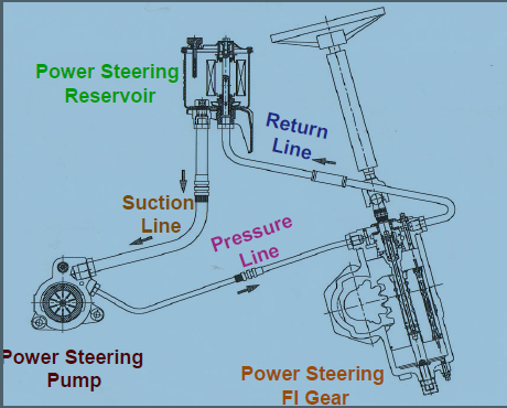
Function to produce fluid pressure. The pump is driven by a belt running from the crankshaft. It supplies the hydraulic pressure needed to operate the steering gear.
Power Steering Pump

Constant or Positive displacement Pump. They deliver different pressure depending on the type and make of the vehicle. They use special power steering fluid recommended by the manufacturer.
In operation, as the center part of the pump turns clockwise, there is a suction produced where the return oil comes in. The suction is produced because at this location, the eccentric area gets larger and larger. Then, because the area gets smaller, a pressure is produced.
Control Valve

It is build directly into the power steering gear assembly to direct the air pressure to one side or the other on the piston and the ball nut assembly. When the steering wheel is turned, the control valve is position in such a way as the direct oil to the correct location. There are two type of control valve:
i) Rotary Spool Valve

Operation:
When the steering wheel is turned, the twisting effort produced through a torsion bar to rotate the internal spool slightly. This is done on an internal spline. As the spool rotates slightly, a different set of ports is opened and closed to allow oil pressure to flow to the correct side of the piston assembly.
ii)Sliding Spool Valve
Operation:
When steering wheel and worm gear is turned, the sliding spool valve moved slightly by linkage attached to the worm gear shaft. The internal spool open a set of ports to allow high pressure fluid to enter the correct side of the piston and the ball nut assembly.
1.2.3 Integral Power Steering System

Basic Operation :
As the worm gear is turned by the steering wheel, the oil pressure is sent to the unit from the power steering pump. Oil is sent to both sides of the piston. This keeps the piston in a stable position. When the car is moving in a straight line, the pressure are equal on both sides of the piston. When the steering wheel is turned, higher oil pressure is directed to one side or the other to assist movement of the piston and the ball nut assembly. Assisting the movement of this assembly makes it easier for the driver to turn the steering wheel.
1.2.4 Rack And Pinion Steering System

For the Rack and Pinion Steering, the pressure from control valve operates the rack assembly. It uses the same principle as the Integral Power Steering.
Basic Operation :
As the power steering pump produces the necessary hidraulic pressure, the fluid is sent to the rack-and-pinion steering gear. The pressure difference across the piston in the center assists the effort on the steering wheel.
1.3 Electronic Power Steering System
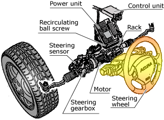
Basic Operation :
As an electrical motor is placed into Rack and Pinion Power Steering, as the motor is turned, it assists the movement to the Rack and Pinion components. Steering effort is greatly reduced and is taken by the motor. It is because the motor are able to rotate in both direction. However, the motor is controlled by a sensor placed in rack and pinion housing , near steering column.
As the driver begin to turn the steering wheel, hydraulic pressure is built up. The increase in pressure is sensed by the steering effort sensor. The sensor is able to select the direction of the motor movement and turn the motor off and on accordingly.
So, in conclusion, as the steering wheel is turned, the steering sensor tells the Electronic Power Steering control unit to send hydraulic fluid and pressure to the steering gearbox. This action assists the steering effort when turning the front wheels.
Advantage of Electronic Power Steering System
Electric power steering can be fine tuned with a precision that is hard to match with hydraulic controls. By monitoring the driver's steering inputs, vehicle speed, and other suspension dynamics, the system can provide just the right amount of steering feel and effort to match rapidly changing driving conditions. EPS can deliver extra effort when you need it, and reduce steering effort when you do not need it. It can even provide steering assist when the engine is off.
So, it ensure the comfort of the chrysler car while driving it.

No comments:
Post a Comment